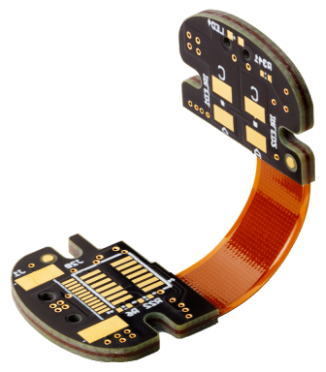
High-Volume Flex and Rigid-Flex PCB Manufacturing

We manufacture high-volume flex and rigid-flex PCBs on a daily basis. Our engineering teams are experts in building flexible electronics and follow strict IPC-2223 and other guidelines to meet customers’ needs.

Email Us for a Quote

Flex and reliability

Modern technology calls for innovative and compact systems, such as fitness trackers and medical monitoring equipment which require circuit boards that can be bent during their operation and occupy less space, reducing the overall size of the product. Flex and rigid-flex PCBs address this issue, allowing manufacturers to create smaller, faster, and flexible devices.

Flex boards are made of very thin substrates with high levels of bendability, which enables them to offer improved resistance to vibrations and movements. A rigid-flex circuit board is a fusion of rigid and flexible technologies.

Common roadblocks to successful flex/rigid-flex design

Flex and rigid flex boards are capable of solving various connectivity and packaging issues as they can bend during their assembly and operation. Depending on the bending requirements (static or dynamic), the design must be crafted in a way that doesn’t damage the copper circuitry. When it comes to rigid-flex boards, the placement of flex sections plays an important role as it directly impacts mechanical reliability via plating and electrical stability. Techniques such as the air-gap construction method are implemented to handle these challenges in higher layer count rigid-flex designs.

A well-designed flex or rigid-flex board should be light-weight, reliable, and easy-to-install. Always consult your CM to make sure your PCB is optimized.

Capabilites Overview

  • Up to 16 layers for rigid-flex
  • Core thickness: .001″
  • Max panel size: 12″ x 18″
  • Min trace and space: .0035″
  • Solder mask registration: .002″
  • Blind and buried vias

Fabrication Plus

  • Routed arrays
  • Edge plating
  • Bevels
  • Countersink
  • Electrical testing
  • 10% impedance tolerance

Certifications

  • ITAR
  • IPC 6012 class 1, 2 & 3
  • AS9100D
  • NADCAP
  • MIL-PRF-55110
  • MIL-PRF-31032/1
  • MIL-PRF-31032/2
  • ISO 9001:2015
PCB attributes
Flex Rigid-flex
Min Layer Count 1 1
Max Layer Count 12 ≤ 16
Min Core thickness .001″ (.025 mm) .002″ (.051 mm)
Max Finished Copper Weight (I/L) 2 oz (59 ml) 3 oz (89 ml)
Max Finished Copper thickness (O/L) 12 micron (.012 mm) 9 micron (.009 mm) (only for O/L)
Max Panel Size 12×18 12×18
Smallest Mechanical Drill Diameter .0079″ (.201 mm) .0071″ (.180 mm)
Smallest Laser Drill Diameter No .005″ (.127 mm)
Min Finished Hole Size .006″ (.152 mm) .006″ (.152 mm)
Max through Hole Aspect Ratio 10:1 10:1
Max Blind Via Aspect Ratio .75:1 .75:1
Min Trace and Space ≥ .0035”(.089 mm) ≥ .0035”(.089 mm)(rigid)
Min Pad Size for Test .016″ (.406 mm) .005” (.127 mm) (rigid)
Process Pad Diameter D + .014″ (.356 mm) (1-mil (.025 mm) annular ring) D + .014″ (.356 mm) (1-mil (.025 mm) annular ring)
Stacked Vias No No
Min Wire Bond Pad Size > .006″ (.152 mm) .006″ (.152 mm)
Controlled Impedance Tolerance 10% 5%
Solder Mask Registration Within .002″ (.051 mm) Within .002″ (.051 mm)
Solder Mask Feature Tolerance .001″ (.025 mm) .001″ (.025 mm)
Solder Mask Min Dam Size .004″ (.102 mm) .001″ (.025 mm)
Min Diameter Route Cutter Available .019″ (.483 mm) .024″ (.610 mm)
Mechanical Routed Part Size Tolerance .003″ (.076 mm) .010″ (.254 mm)
Bow and Twist Tolerance N/A As per spec
Thickness Tolerance +/- .002″ (.051 mm) 10%
Sequential Laminations N/A 2
Buried Vias Yes Yes
Blind Vias Yes Yes
Conductive Filled Vias No Yes
Non Conductive Filled Vias No Yes
Surface finishes
Flex Rigid-flex
HASL (Vertical or Horizontal) Yes (not recommended) Yes
Lead Free HASL Yes (not recommended) Yes
OSP (Shikoku F2) Yes (not recommended) Yes
OSP (Entek) Yes (not recommended) Yes
ENIG (Electroless Nickel/Immersion Gold) Yes (most common) Yes
Immersion Silver Yes (not recommended) Yes
Immersion White Tin No No
Tin Nickel No No
Electrolytic Soft Gold Yes Yes
Electrolytic Hard Gold Yes Yes
Selective Gold Yes Yes
Solder mask color
Rigid-flex Rigid-flex
Amber Yes Yes
Green Yes Yes
Black No Yes
Red No Yes
Blue No Yes
Yellow No Yes
White No Yes
Clear NO Yes
Bright White No Yes
Purple No Yes
Legend
Flex Rigid-flex
White Yes Yes
Fab
Flex Rigid-flex
Routed Array Yes Yes
V Score, Edge to Copper .002″ (.051 mm) .01″ (.254 mm)
V Score Angles No Yes
Countersink Yes Yes
Counterbore Yes Yes
Bevel Yes Yes
Milling Yes Yes
Edge Castellation Yes Yes
Edge Plating Yes Yes
Heatsinks No No
Electrical test
Flex Rigid-flex
10 Volt Yes Yes
40 Volt (Burn-In Boards) Yes Yes
250 Volt Yes Yes
500 Volt Yes Yes
Laminate materials
Flex Rigid-flex
Flexible Poyimide Yes Yes
Arlon 85NT No No
Bergquist No No
Hybrid Constructions Yes Yes
Isola FR406 Yes Yes
Isola FR408 HR Yes Yes
Isola P95 Isola P95 Isola P95
Isola P96 Yes Yes
Iteq IT180 Yes Yes
Panasonic R1766 Yes Yes
Panasonic R1755 Yes Yes
Panasonic Yes Yes
Nelco N4000-13 Yes Yes
Nelco N4000-29 Yes Yes
Nelco BT N5000 Yes Yes
Nelco N7000-2 Yes Yes
No Flow Prepreg Yes Yes
Isola 370HR Yes Yes
Polyclad Getek No No
Bond Yes Yes
Rogers No No
Rogers R4000 Series No No
Rogers 5000 Series No No
Rogers 6000 Series No No
Rogers TMM No No
Available reports
Flex Rigid-flex
Microsection Yes Yes
Solderability Yes Yes
X-Ray Fluorescence Yes Yes
Ionic Contamination Yes Yes
Time Domain Reflectometry Test (TDR) Yes Yes
FAI Yes Yes
Certificate of Compliance Yes Yes
UL
Flex Rigid-flex
94VO Yes Yes
PCB classifications mil-spec
Flex Rigid-flex
MIL-PRF-55110 No No
MIL-PRF-31032/1 No No
MIL-PRF-31032/2 No No
IPC 6012, Class 1, 2 and 3 Yes Yes
ISO 9001:2015 Yes Yes
ISO 13485:2016 Yes Yes